Precision Part Digitisation Service for Complex Components India
Convert complex physical parts into fully editable, parametric CAD models and reverse-engineered digital twins with certified metrology precision.
When Standard Scanning Gets the Shape but Misses the Precision
Standard Digitisation
Precision Digitisation
Shape Mimicry
Mesh looks visually correct, but hides critical geometrical deviations.
True Point Cloud Accuracy
Traceable, sub-millimeter accuracy mapped explicitly to raw scan data.
Surface Smoothing Loss
Automated smoothing algorithms destroy critical curvature continuity.
Class-A Surface Fidelity
NURBS reconstruction preserves exact G2 and G3 curvature continuity.
Feature Degradation
Sharp edges and micro-features are frequently rounded off and lost.
Exact Feature Reconstruction
Sharp edges, deep cavities, and micro-features are explicitly rebuilt.
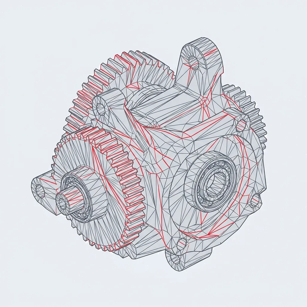
Manufacturing Risk
Very high risk of failure during CNC machining or assembly.
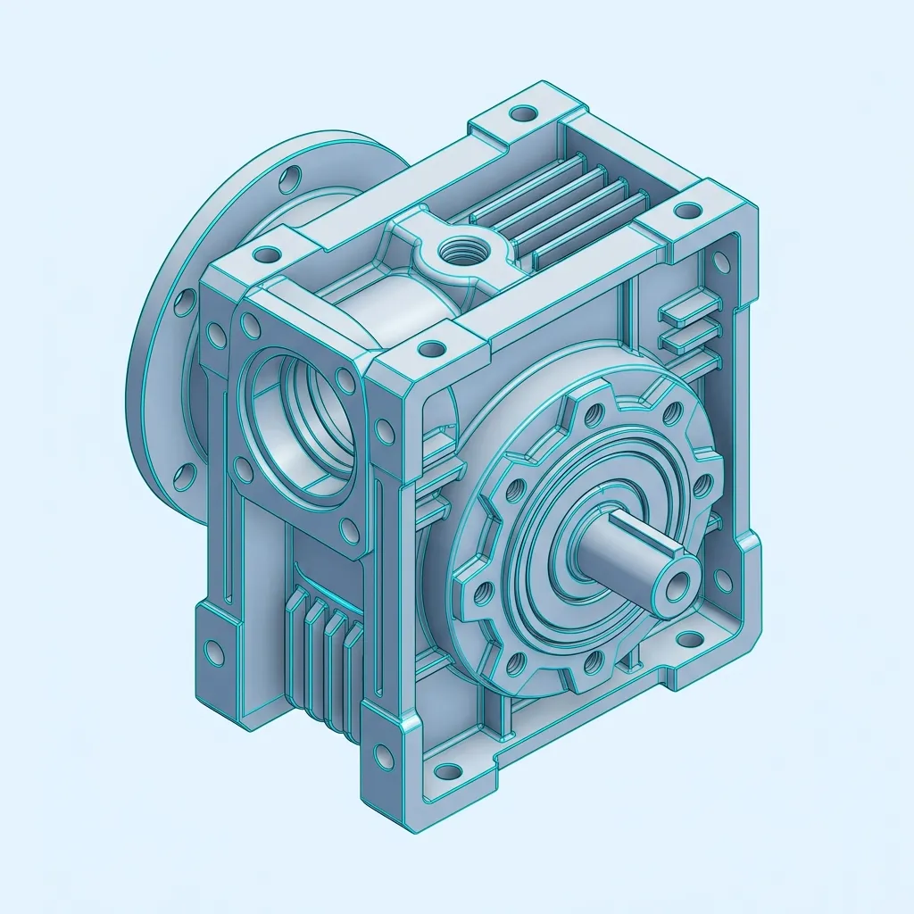
Production Ready
Delivers audit-ready, manufacturing-grade CAD models for instant production.
What Makes Complex Component Digitisation Technically Different
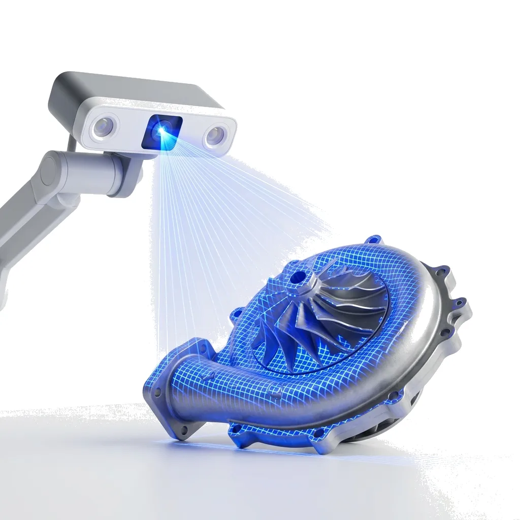
Scanner Accuracy
Crucial for Turbine blades, Bearing surfaces, and intricate Mould inserts.
Surface Fidelity
Maintaining NURBS geometry, exact Curvature continuity, and clean Reconstruction.
CAD Output Model
Audit-ready format for FEA, Toolpaths, Inspection, and Manufacturing workflows.
High Accuracy 3D Digitisation Service for Aerospace and Automotive India
Complex Geometry Digitisation Using 3D Scanning India
Freeform Surface Digitisation Service for Manufacturing India
Curvature Continuity

Premium CATIA-Style Surfacing
We don't just patch surfaces. We reverse engineer the design intent using pure, untrimmed NURBS patches for flawless manufacturing.
- ✔️ Class-A Surfaces
- ✔️ Mould Cavities & Core
- ✔️ Complex Turbine Profiles
- ✔️ Precision Tooling Components
Precision CAD Modelling from 3D Scan Data India
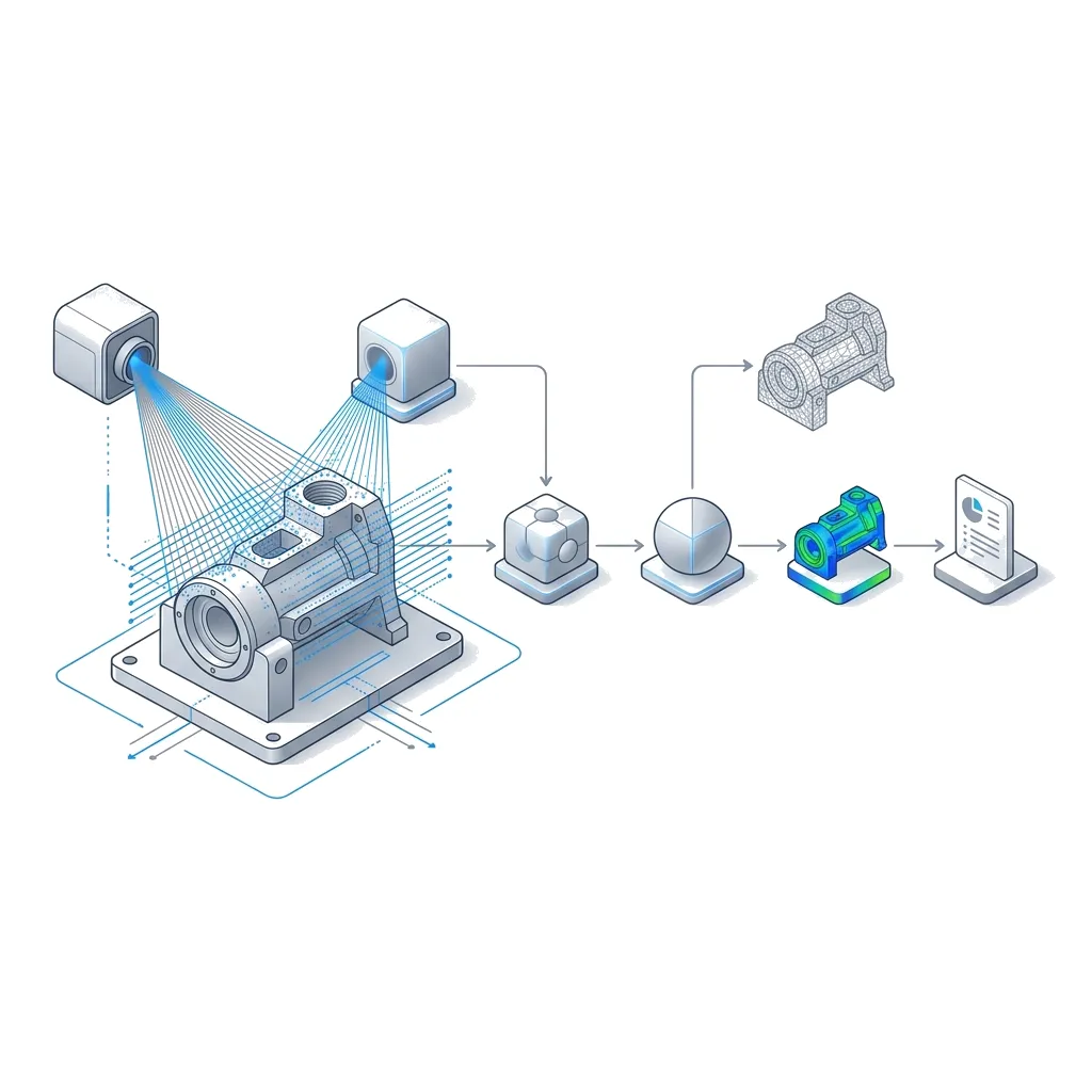
RAW SCAN DATA
- Point Cloud
- Noise
- Feature Data
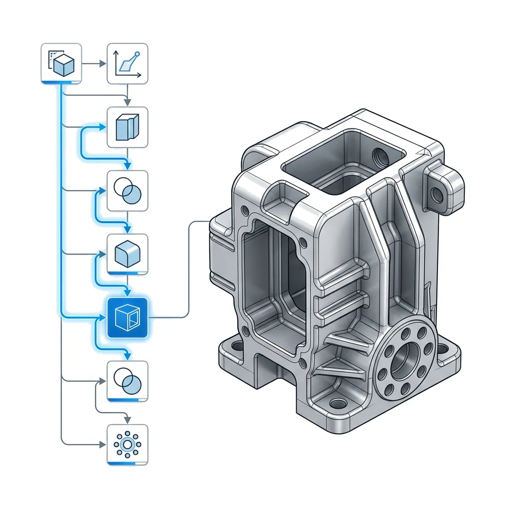
FEATURE RECONSTRUCTION ENGINE
FINAL CAD
- Bores & Planes
- Fillets
- NURBS Surfaces
Deviation Report Preview
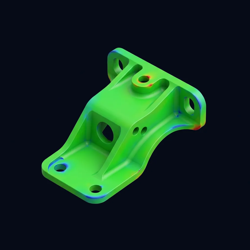
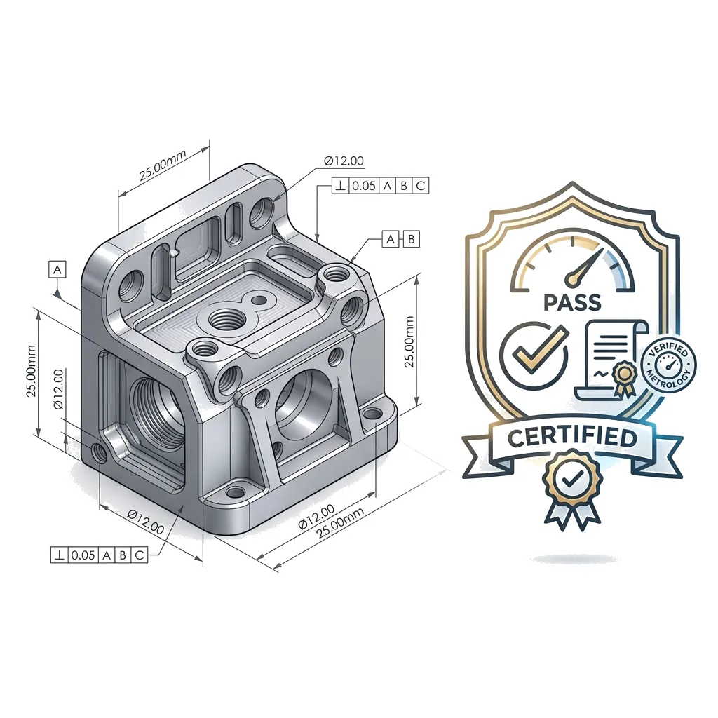
Precision Assurance Framework
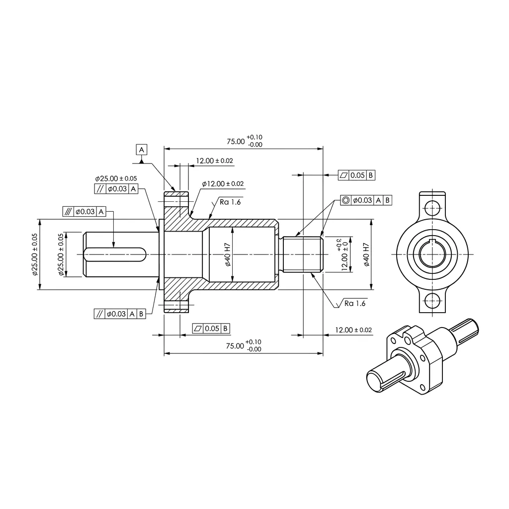
What is Precision Part Digitisation Service for Complex Components India?
Physical Part Digitisation is the process of converting a complex physical component into a fully editable, parametric CAD model or reverse-engineered digital twin, using certified 3D scanning and metrology to capture surface geometry with dimensional precision.
When to Select This Service
Choose part digitisation when you need to recreate a parametric CAD model for a complex component that has no source CAD data, capture an accurate digital twin of an existing part, or feed reverse-engineered geometry into downstream design or manufacturing.
Technical Capabilities & Verification Standards
Verified engineering parameters, hardware precision, and compliance benchmarks applied across all deliverables.
| Engineering Parameter | APJ 3D Capability & Precision Range | Compliance Standard / Verification |
|---|---|---|
| Scanning Hardware | Creaform HandySCAN 3D, MetraSCAN 3D, ZEISS GOM ATOS Blue Light, FARO Laser Trackers | VDI/VDE 2634 Part 3 Certified |
| Volumetric Accuracy | Up to 0.020 mm (20 µm) + 0.040 mm/m over large volumes | ISO 17025 Traceable Calibration |
| Part Size Range | From 10 mm precision clips up to 20+ meter automotive bodies & aircraft structures | Portable On-Site & Lab Inspection |
| Surface Resolution | Mesh grid resolution down to 0.050 mm (50 µm) | High-Density Micro-Feature Capture |
| Output Deliverables | High-density STL, OBJ, PLY, Native STEP/IGES CAD, Colour Error Deviation Maps, PDF Reports | ASME Y14.5 Inspection Reports |
| Measurement Speed | Up to 1,300,000 measurements/second (Dual Blue Laser Cross) | Rapid Real-Time Data Acquisition |
| Turnaround Time | On-site scanning: Same-day / 24h; Full CAD/Inspection reports: 2 to 4 business days | Pan-India On-Site Mobilization |
Frequently Asked Questions
What is physical part digitisation?
What is physical part digitisation?
How is precision digitisation different from standard scanning?
How is precision digitisation different from standard scanning?
When should I digitise a part?
When should I digitise a part?
How do I get started with part digitisation?
How do I get started with part digitisation?
Need Precision 3D Digitisation
for Your Complex Components?
Upload your component details and receive a realistic digitisation plan, delivery timeline, and scanning strategy from APJ 3D's dedicated metrology team. We convert physical parts into traceable, engineering-grade CAD models for aerospace, automotive, and heavy engineering sectors.